Installation Guidelines
GeyserTECH+ Pi²R Installation Guidelines
Important: These instructions are an abbreviated guide to configuring the system and all local regulations regarding electrical connections should be adhered to.
- Note: Part 1 of the installation guide refers to installation of the optional Digital Display which can be paired with the GeyserTECH+ Pi2R iX controller.
- Part 2 of the guide is applicable to both the GeyserTECH+ Pi2R Micro and GeyserTECH+ Pi2R iX controllers..
Part 1: Installation of the optional Pi2R Digital Touchscreen Display (applicable to GeyserTECH+ Pi2R iX only) (for installation of the Micro or iX controllers, skip to Part 2)
Note: The Digital Display screen fits onto a standard 4x4 PVC electrical box,
Step 1: Communication Cables
First of all, we prepare the wires as shown in the image below.
NOTE:
Multi-strand wire is not compulsory, but we do recommend multi-strand as it can handle being bent better than what solid core can.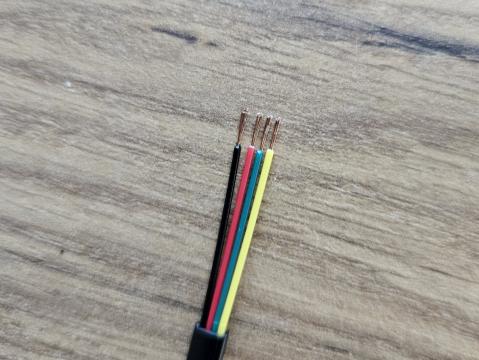
Next is to connect your prepared wires into the supplied connector block. The color codes are the same for both connectors, and because both connectors are the straight type, pin 1 is typically not marked.
You may remove additional wires as to only use three cores of a four core cable for example.
However in this example we simply tied the green and yellow wires together for neatness.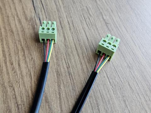
NOTE:
It is good practice to double-check your conductivity using a standard multi-meter.
Because the display's wires are connected to one straight connector block and one right-angled connector block, pin 1 is typically marked to avoid confusion (see black dot in pic). We supply a right-angle connector for the display unit so as to easily fit into the tight space where the display is installed. The straight connector is intended to be used on the controller unit side where there is less of a space constraint. When looking from the terminal pins as reference the color codes are in the same order for both connectors, as shown in the picture.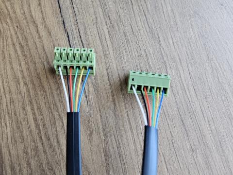
Step 2: Testing
Connect the wires to the power unit (controller) as shown in the picture and connect the other ends to the display unit and thermometer respectively. Then power up the unit with either AC or DC power, no need for both at this stage.
Note
If your Display battery is charged above 3.9V, the display can power the main unit and testing can be done without powering up the main unit separately.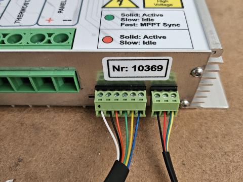
An error message will be displayed if the display unit cannot communicate with the power unit. Please remove power from the main unit and double-check the 6-core cable connections for faults if this occurs.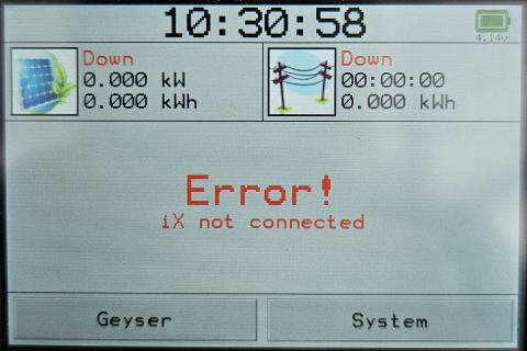
The next error will occur when the power unit cannot communicate with the thermometer. Please remove power from the main unit and double-check the 3-core cable for faults.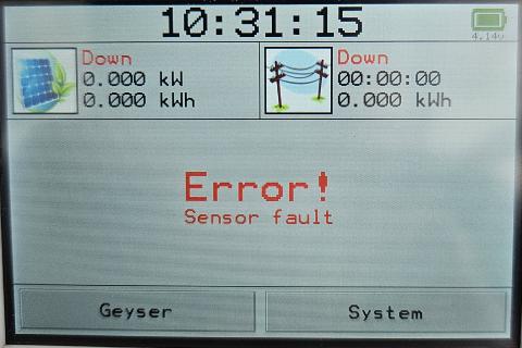
When both communication cables are working properly, you should see a temperature reading as shown in the next picture.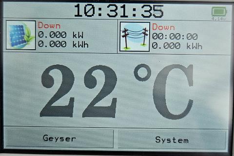
Finally go into the menus under “System” and “About”.
Check that the battery is charging. The third line should say something like Battery: 4.2 v, Active.
The four possible modes are:
- Full
- The battery is currently full and will remain in standby.
- Active
- The battery is charging.
- Suspend
- This usually happens in extreme weather conditions. For safety, the battery only charges in ambient temperatures from 15-45 Celsius.
- Fault
- This is normal when the main power unit does not have incoming power to supply the display.
- However it can indicate a fault on the 6-core wire, specifically Pin-2 (Black wire in the example)
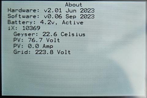
The readings from the power unit are also shown for verification.
In the above example the photovoltaic (PV) panels deliver 76.7 Volt DC and Grid power is currently on 223.8 Volt RMS.
Step 3: Thermometer and Thermostat
The example shows how to connect to a spiral element and thermostat. If your geyser has a long element and separate thermostat, your installation is much simpler.
Simply do the following:
- Remove the thermostat completely
- Insert the thermometer into the thermal pocket
- Secure so that it stays inside the thermal pocket
- Wire the Pi2R iX unit directly to the element terminals
The supplied thermometer probe needs to measure the water temperature inside the geyser. Firstly, check that the thermal pocket is clean and dry. The white adhesive tape attached to the flexible circuit board is available to stick the sensor directly to the thermostat. Before reinserting the thermostat with the attached thermometer probe, it is important to ensure that the mouth of the thermostat pocket will not pinch the flexible circuit board. It may be necessary to widen or shorten the mouth of the pocket with a suitable tool.
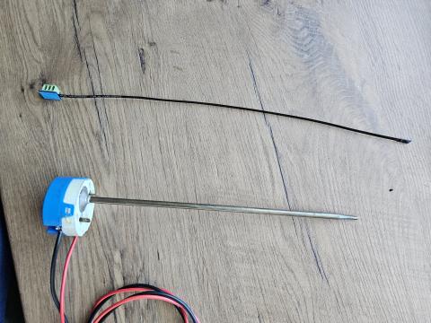
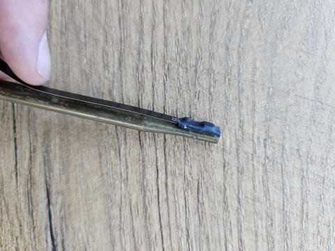
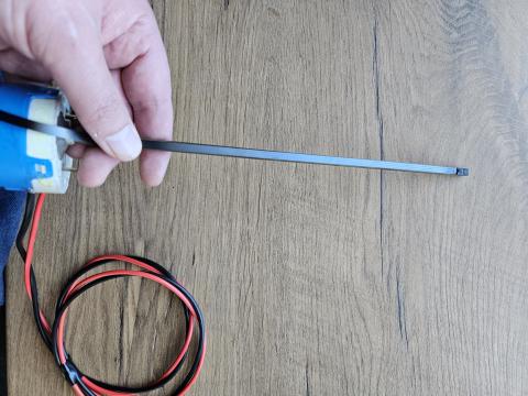
Two different kinds of thermostats are shown in the next pictures. Before sticking the connector block on, check that the connector block attached to the wire will not get obstructed when plugged in. Select a convenient placement for the connector and stick it onto the thermostat.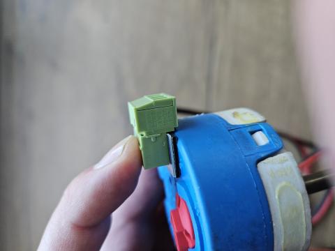
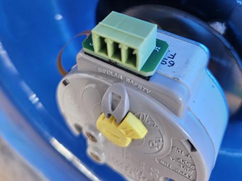
Next set the thermostat to maximum (70 Celsius for most geysers). The existing thermostat will function as a convenient connection point to the element itself and also as a safety backup by tripping the power if the water temperature reaches beyond the set point.
Finally insert the thermostat with thermometer into the element, being careful not to damage the electrical connectors of the element.
Part 2: Installation of the GeyserTECH+ Pi2R controller (applicable to both the Micro and iX)
Step 1: DC Cables
Install MC4 connectors onto chosen cables, making sure that POSITIVE (RED) and NEGATIVE (BLACK) are CONNECTED CORRECTLY.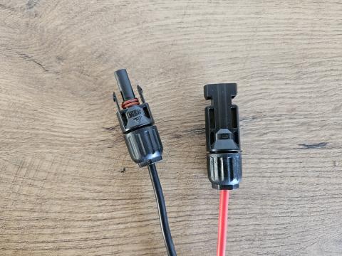
Next is to connect your prepared wires directly to your Micro or iX unit (via appropriate fusing).
NOTE:
It is good practice to install in-line fuses (not shown in the picture) in the DC cables so as to protect against a fault or short circuit in the wiring or inside the Pi2R unit (15A recommended).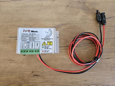
NOTE:
It is good practice to double-check your polarity using a standard multi-meter.
Step 2: Thermostat
It is generally not necessary to remove the thermostat from the geyser for this step. The thermostat in the picture was only removed to be able to show detailed pictures.
Install wires to the existing thermostat and set to the clients' required temperature on the thermostat.
The Pi2R controller will choose between either AC power or DC power and always feed the thermostat with the appropriate power. The thermostat will monitor and control the water temperature, not the Pi2R unit.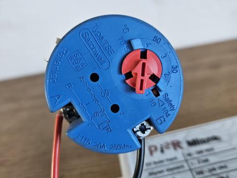
If the geyser has a non-standard thermostat, connect as if the wires would have come directly from AC power.
Connect the other end of the thermostat wires to the Pi2R controller.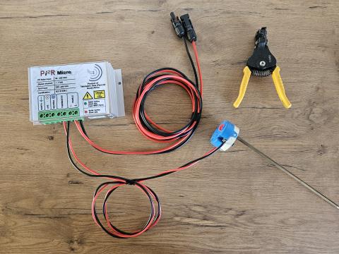
At this point you are done with the DC solar side. For off-grid installations you may proceed to Step 4 and finish up, but keep in mind that it is still required to connect an earth wire as normal.
Step 3: AC Power
Connect Earth, Neutral and Live wires from your isolator switch to the Pi2R unit as shown in the picture. If installing without the optional Digital Display and also connecting to AC grid power, then a geyser timer should be installed so as to limit AC availability to required times.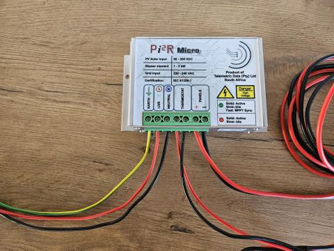
Step 4: Finishing
Now that everything is connected:
- Plug the thermostat into the geyser element
- Inspect the element connectors for any damage and repair if needed. The element draws considerable amounts of amps and hot connections can be very dangerous.
- Connect the MC4 connectors to the PV panels
- The element should start drawing power at this point.
- Switch on AC power and set up DB Timer
- For maximum savings, the timer should feed power about an hour or two before water use and ideally stop feeding power shortly before water use.
NOTE:
- When the geyser is warm enough, AC power will be available but not used.
LED indicator:
- Solid green: The Micro is feeding PV to the thermostat/element and the water is cold enough to still draw power.
- Flashing green: The Micro is feeding PV to the thermostat/element, however the water is warm enough that the thermostat is switched off.
- Solid red: The Micro is feeding AC to the thermostat/element and the water is cold enough to still draw power.
- Flashing red: The Micro is feeding AC to the thermostat/element, however the water is warm enough that the thermostat is switched off.
- Alternating Red/Green: The PV power is measured every 10 minutes and the appropriate weather conditions recalculated to maximize power harvesting.
COMPLIANCE
- All wiring must be installed in accordance with all local regulations. Power wiring must conform to the local electrical code. Use of a qualified contractor and approval by the local authority ensures compliance to this code
- The grounding system must be installed in accordance with the SABS Electrical Code, and any other applicable electrical codes. (To include: IEEE-142; Lightning Protection Institute Installation Code LPI-175; NFPA-78 (ANSI); IEEE Std. 142-1972; Code LPI-175)
